EPFL Day 2: Mechanics & CAD Design
While Day 1 was all about coding the “brain,” Day 2 focused entirely on the “body.” We learned that a solid mechanical design is fundamental for a robot’s performance, stability, durability, and safety[cite: 285]. It directly impacts weight distribution, power efficiency, and payload capacity.
Key Principles of Robot Design
Before touching any software, we covered the core principles of building a chassis:
- Stability: Keeping a low center of gravity and a wide base to prevent tipping.
- Mobility: Choosing the right wheel setup for the desired movement.
- Modularity: Designing parts that are easy to assemble, swap, and maintain.
Designing in Tinkercad & Laser Cutting Prep
The journey from a digital concept to a physical frame involves two main phases: CAD design and manufacturing.
We started by using Tinkercad. To get familiar with the software, we designed a Swiss flag. This practical exercise taught us a crucial trick for laser cutting: setting objects “below the floor” in Tinkercad. This technique creates the precise outlines that the laser cutter follows to cut or engrave.
After mastering the basics, we took a pre-existing 3D chassis model and modified it to design our own custom robot. The goal was to prepare a digital model that could be physically cut out of 3mm thick plexiglass sheets using a laser cutter.
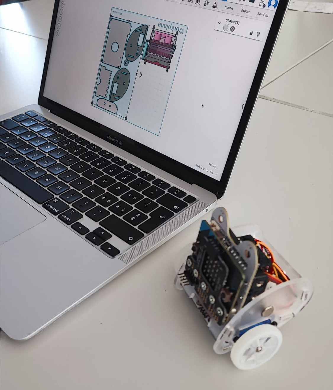 Designing the 3D model and setting up the precise cuts for the laser.
The Glowforge laser cutter bringing our digital Tinkercad design to the physical world.
Assembly and Troubleshooting
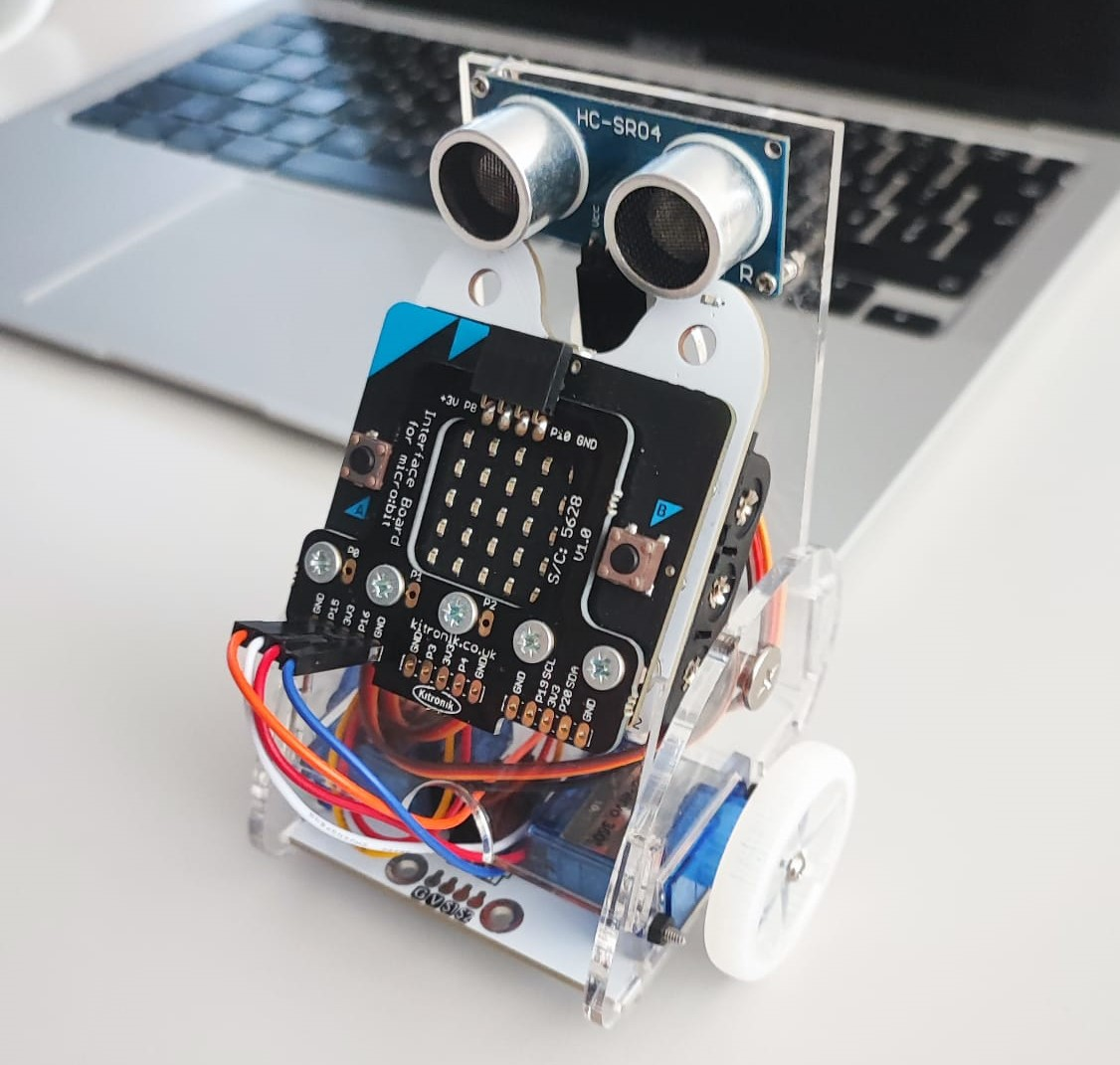
Once our plexiglass parts were ready, it was time for assembly. We mounted the Micro:bit interface board, the HC-SR04 ultrasonic sensors, the DC motors, and the custom transparent chassis pieces.
Putting everything together we learned that there are several factors we had to keep in mind:
- Friction: Identifying parts rubbing against each other that strain the motors.
- Alignment: Fixing wobbly or jammed wheels.
- Structural Integrity & Fasteners: Ensuring screws were tight and the design could handle pressure without breaking.
We ended the day by touching upon Kinematics—understanding how wheel rotations translate into the robot’s actual forward, backward, and turning movements. With the physical robot fully built and structurally sound, we were finally ready to make it move!
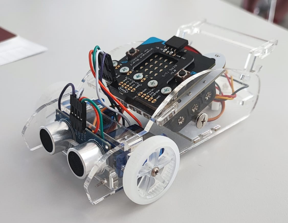
Testing the final assembly of our custom mobile robot.